I am going to assume you have rebuilt your entire suspension, shiny new subframes with all new busings and bearings? Good, then we will begin.
If you have access to a OBD tool that can wipe the ride height offsetts then do this first so everthing is zeroed. Its not ‘essential’ but its better if you can.
Ensure the car is parked on flat gound.
load the car as you expect to drive it, spares, jack etc etc
check the tyre pressures
Engine running, set the ride height to standard and drive it back and forth to settle the tyres on the road.
Engine off and door open jack the car up on each corner and disconnect the drop links to the anty roll bars front and rear
with the tyres back on the ground roll the car again to settle the tyres.
What we are trying to do next is first set the ride height front and rear, then ‘ballance’ the car side to side.
Now if we had 4 corner scales we could set them up and as we adjusted the drop links we could make sure the car placed the same load on each tyre patch. I dont have corner scales so we are going to use a tape measure!
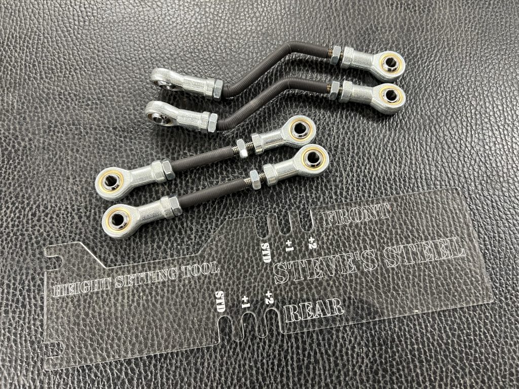
Run round each corner of the car and using the supplied guage roughly set the desired height.
If you have the patience then put a jack under the front of the car and lifting in exactly the centre of the front sub frame get the front wheels off the road. You now have a ‘three legged’ car 🙂
Returning to the back of the car open the back doors and from the sharp outer edge of the sill measure to the ground, if the suspension is active and you have the rods set correctly these measurements will be the same on both sides and while we are at it, the load on the tyre contact patches will be the same.
Drop the front to the ground and reverse the process jacking the back and levelling the front.
With all four wheels on the ground you car should now be sitting nicely at its new ride height.
Before we go for a drive we need to re connect the anty roll bars. If you are replacing the stock drop links then just bung them on but you might notice that when you try to connect the second side of the bar the links will be the wrong length. This is due to the built in stresses and manufacturing tollerances in the suspension components. On a stock car we would just bang them in but when we do this we build back in some forces that will be fighting against the suspension.
Remember the anty roll bar should not be applying any forces if the car is not rolling so use the adjustable drop links we supply for the anty roll bars.
In the set one link for the front and one for the rear will already be locked to lenght, put this one on first then on the opposite side adjust the lenght to the point where it just slides on without deflecting the roll bar at which point the setup is complete.
CHECK EVERYTHING IS TIGHT
CHECK YOU HAVE REPLACED EVERYTHING
And go for a slow test drive before returning and checking using your tape measure that everything is still level.
Things to watch out for;
When the car has been running at one height for a while and you then move it you may hear new squeeks and other noises from the suspension. Do not ignore them! You may need to slacken and re tighten all the suspension links and bolts through busings at the new ride height to let the stresses out of the system.
This article discusses the air suspension system fitted to the L322 Range Rover from 2003 on.
I am interested in what happens when we adjust the ride height, from my perspective, for off road driving. What breaks and how to set the suspension up.
The following description of how the suspension works comes directly from the workshop manual and should be reviewed and understood before embarking on any changes to your suspension.
General
The main function of the four corner air suspension system is to maintain the vehicle at the correct ride height, irrespective of load. Additionally, the system allows the driver to request ride height changes to improve off-road performance or ease of access or loading. The system automatically adjusts the ride height to improve the vehicle handling and dynamics when speed increases or decreases.
The system will temporarily inhibit height adjustments when the vehicle is subject to cornering, heavy acceleration or heavy braking. The inhibit function prevents unsettling of the vehicle by reducing the effective spring rates.
Height changes are also inhibited for safety reasons, when a door is opened and the vehicle is stationary for example.
The air suspension system fitted to Range Rover is controlled by an ECU located behind the passenger side of the fascia. The ECU monitors the height of each corner of the vehicle via four height sensors, which are mounted in-board of each road wheel. The ECU also performs an ‘on-board diagnostic’ function to perform ‘health checks’ on the system. If faults are detected, codes are stored in the ECU and can be retrieved using TestBook/T4.
The independent front and rear suspension offers many design and performance advantages over the conventional beam axle design.
Front Suspension
The independent front suspension offers a reduction of un-sprung mass over the conventional beam axle design. Thesuspension geometry features positive ground level off-set for improved control under braking. The suspension arms have been designed for maximum ground clearance. Suspension geometry can be adjusted via the strut top mount for camber and on the steering rack track rod ends for toe-in.
Front suspension features a 6mm positive off-set.
The following wheel travels are shown for on road and off-road vehicle operation. The difference between the two operating conditions is a result of operation of the front cross-link valve. When the cross-link valve is opened the suspension travel is as given for off-road wheel travel. When the cross-link valve is closed the suspension travel given for on road applies.
The off road mode wheel travel is:
175 mm bump
95 mm rebound
This gives a total of 270 mm off road suspension travel.
The on road standard wheel travel is:
115 mm bump
155 mm rebound
This gives a total of 270 mm on road suspension travel.
The front suspension comprises:
Two air spring damping struts
Subframe
Anti-roll bar
Anti-roll bar links
Suspension arms
Two hub assemblies
Front Subframe
The front subframe is fabricated from steel tubing to provide a robust platform for the mounting of the suspension and engine. The subframe is attached to the vehicle body via six mountings.
The subframe fabrication provides accurate location for the suspension components and the steering rack. Additional brackets allow for the attachment of the height sensors and the engine mountings. The anti-roll bar is attached across the rear of the subframe and is mounted in flexible bushes which are secured with ‘D’ shaped clamp plates.
Anti-Roll Bar and Links
The anti-roll bar is fabricated from 30mm diameter, solid spring steel bar. The anti-roll bar operates, via a pair of links, from a bracket mounted on each strut.
The anti-roll bar is attached to the rear of the subframe with two bushes which are bonded to the bar and cannot be removed. Clamp plates are pressed onto the bushes and must not be removed. The anti-roll bar is secured to the subframe with the clamp plates which are located on studs on the subframe and secured with nuts.
The ends of the anti-roll bar are attached to each strut spring seat via an anti-roll bar link. This arrangement allows the anti-roll bar to act on a 1:1 ratio with the wheel travel providing maximum roll bar effectiveness. A hardened washer is fitted between the ball joint and the strut mounting plate. The hardened washer prevents the ball joint damaging the bracket, which could lead to loosening of the torque on the nut. When the link is removed from the strut, it is important to ensure that the correct hardened washer is replaced in the correct position.
Each anti-roll bar link has a ball joint fitting at each end which improves response and efficiency. The top ball joint is mounted at 90° to the axis of the link and attaches directly to the strut and is secured with a locknut. The lower ball joint is mounted at 90° to the axis of the link. The ball joint attaches to the anti-roll bar and is secured with a locknut.
The link must be attached to the anti-roll bar with the ball joint on the outside of the bar and the locknut facing inwards. The ball joints on the anti-roll bar links are not serviceable and if replacement of either is necessary, a new anti-roll bar link will be required.
Suspension Links Transverse Link
The front suspension hub assembly is secured to the subframe via two suspension links. Each transverse link is fitted with a bush which is secured with a bolt between two brackets on the subframe. The opposite end of the transverse link is fitted with a ball joint which attaches to the hub assembly.
Compression Link
The compression link is located rearward of the transverse link. The compression link is fitted with a compliance bush which is secured with a bolt between two brackets on the subframe. The opposite end of the compression link has a tapered hole which locates on a ball joint which is bolted to the hub assembly.
Hub Assembly
The hub assembly comprises a swivel hub, drive flange and bearing. A seal and bearing are fitted in the swivel hub and are secured with a circlip. The drive flange has the wheel studs attached to it and locates on the splined drive shaft and is secured with a stake nut.
The forged swivel hub has a vertical boss with two cross holes. This provides location for the strut assembly which is secured with bolts and nuts to the swivel hub. Two additional bosses provide location for the brake calliper.
The lower part of the swivel hub has two threaded holes which allow for the attachment of the ball joint which locates the outer end of the compression link. A further tapered hole allows for the attachment of the transverse link ball joint.
A hole is machined at 90° to the hub bearing. This hole allows for the fitment of the ABS speed sensor which is secured with a screw into an adjacent threaded hole. The speed sensor reads off a target which is part of the drive shaft assembly
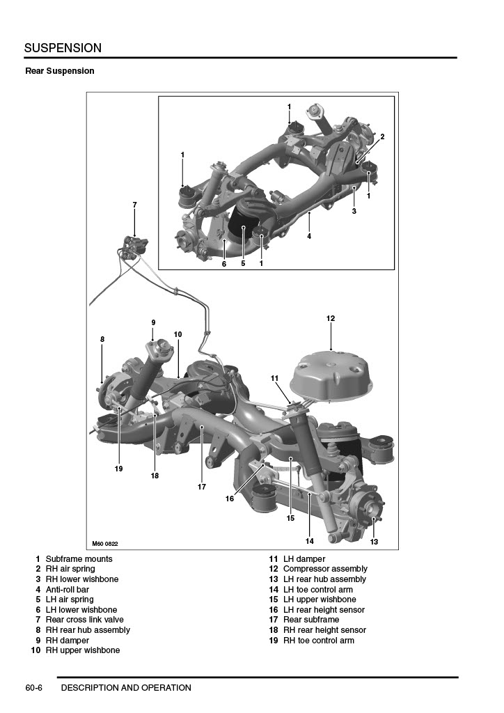
Rear Suspension
The independent rear suspension offers a reduction of un-sprung mass over the conventional beam axle design. The suspension arms have been designed for maximum ground clearance. Wheel alignment can be adjusted for camber and toe-in using eccentric bolts.
The following wheel travels are shown for on road and off-road vehicle operation. The difference between the two operating conditions is a result of operation of the rear cross-link valve. When the cross-link valve is opened the suspension travel is as given for off-road wheel travel. When the cross-link valve is closed the suspension travel given for on road applies.
The off road mode wheel travel is:
190 mm bump
140 mm rebound
This gives a total of 330 mm off road suspension travel.
The on road standard height wheel travel is:
140 mm bump
190 mm rebound
This gives a total of 330 mm on road suspension travel.
The rear suspension comprises:
Two dampers
Two air springs
Subframe
Two upper wishbones
Two lower wishbones
Two toe control arms
Anti-roll bar
Anti-roll bar links
Two hub assemblies.
Dampers
The rear dampers are unique to New Range Rover and are of a mono-tube design manufactured by Bilstein. The mono-tube design gives the following advantages over conventional twin tube dampers:
Lightweight construction
Excellent high frequency response
Consistent performance – mono-tube design eliminates fluid aeration and emulsification
Larger diameter piston produces increased fluid displacement for a given damper stroke resulting in more accurate damping control.
The damper comprises a single tube which forms the operating cylinder. The lower end of the cylinder has an eye which accepts the bush for mounting to the lower wishbone. A piston and rod slides inside the cylinder. The rod emerges from the top of the cylinder which is fitted with a rod guide and a seal.
A dust cover is fitted to the top of the rod and protects the rod from damage. A bump stop is fitted to the top of the piston rod, under the dust cover, and protects the damper from full travel impacts. A top mount is fitted at the top of the piston rod and is secured with a flanged nut. A hardened washer is fitted between the shoulder on the piston rod and the bump washer which is fitted inside the dust cover. When the damper is removed and replaced, care must taken to ensure that the correct hardened washer is refitted in the correct position. The washer prevents the pistonrod shoulder causing damage to the bump washer.
The piston is fitted with reed valves which cover a series of holes, through which oil can pass. A chamber at the base of the damper is sealed by a free floating piston. The chamber is filled with inert gas. When the damper is assembled and filled with oil, the gas is in a compressed condition below the piston. On the bump stroke, the downward movement of the piston displaces oil from the full area (bottom) of the cylinder to the cylinder annulus (top). The energy required to pump the oil through the piston drillings and reed valves creates the damping action.
As the piston moves downwards, the volume available on the annulus side of the piston is less than required by the displaced oil from the full area side. When this occurs, the free floating piston moves downwards, further compressing the gas and providing the additional volume for the displaced oil and further enhancing the damping process
The dampers are located between the lower wishbone and the vehicle body. The lower mounting is fitted with a bush which provides for the attachment to the wishbone with a bolt and nut. The damper top mounting is located in a turret in the body and secured to the body with three nuts. A paper gasket is located between the damper top mounting and the body and prevents the ingress of dirt and moisture into the mounting studs and corresponding holes in the body.
It is important that this gasket is discarded and replaced with a new item when the damper is removed.
Air Springs
Each air spring comprises a top plate assembly, an air bag and a base piston. The air bag is attached to the top plate and the piston with a crimped ring. The air bag is made from a flexible rubber material which allows the bag to expand with air pressure and deform under load. The top plate assembly comprises the plastic top plate with a spigot which protrudes through a hole in the subframe. On the side of the top cap is a connector which allows for the attachment of the air hose from the cross-link valve. The piston is made from plastic and is shaped to allow the air bag to roll over its outer diameter. The base of the piston has a splined stud in the centre and an offset timing peg for correct orientation of the air spring into the lower wishbone.
The air springs are located rearward of the dampers and are retained between the subframe and the lower wishbone.
The air spring is attached to the lower wishbone with a screw which is fitted from the underside of the wishbone into the splined stud on the base of the piston. The air spring top plate is attached to the subframe via an integral ‘D’ shaped spigot which is secured with a retaining clip.
Subframe
The subframe is fabricated from steel tubing to provide a robust platform for the mounting of the suspension and the rear differential. The subframe is attached to the vehicle body via four, voided rubber mounts.
The subframe provides location for the suspension components and the rear differential. Two bushes at the front of the subframe and one at the rear allow for the attachment of the rear differential. Additional brackets, bolted to the subframe, allow for the attachment of the height sensors. The anti-roll bar is attached across the rear of the subframe and is mounted in flexible bushes which are secured with ‘D’ shaped clamps.
Upper and Lower Wishbones Upper Wishbone
The steel fabricated upper wishbone has two bushes pressed into housings which provide for the attachment to the subframe. The bushes are located between brackets on the subframe and are secured with bolts and nuts. The outer end of the upper wishbone has two brackets with slotted holes. A boss on the hub is fitted with a ball joint which locates between the brackets and is secured with an eccentric bolt, washer and nut. This allows for the adjustment of the rear wheel camber. Rotation of the bolt moves the eccentric head against a recessed slot in the bracket, moving the location of the hub in the upper wishbone slots, allowing the camber to be adjusted to within the set limits. A rubber bump stop is fitted centrally on the upper wishbone to cushion the wishbone movement when the suspension is at the extremes of its travel.
Lower Wishbone
The lower wishbone is larger than the upper wishbone and is a steel fabrication. Two bushes are pressed into the wishbone and provide for the attachment to the subframe. The bushes are located between brackets on the subframe and secured with bolts and nuts. The lower wishbone has a platform which provides for the attachment of the air spring. A welded bracket allows for the attachment of the anti-roll bar link. A boss on the hub is fitted with a ball joint which locates between brackets on the lower wishbone. The hub is secured to the lower wishbone with a bolt and nut.
A bracket with a tubular extension provides for the attachment of the damper lower mounting.
Toe Control Arms
The toe control arm is a forged steel component. One end is fitted with a taper ball joint and the opposite end has a bush pressed into an integral housing.
The bush locates between brackets on the subframe and is secured with a special eccentric bolt, washer and nut. This allows for the adjustment of the rear wheel toe in. Rotation of the bolt moves the eccentric head within a recessed slot in the bracket, allowing the toe-in to be adjusted within the set limits.
The taper ball joint locates in a tapered hole in the hub and is secured with a nut.
Anti-Roll Bar and Links
The anti-roll bar is fabricated from 23 mm diameter, solid spring steel. The anti-roll bar operates, via a pair of links, from a bracket on the upper face of each lower arm.
The anti-roll bar is attached to the rear of the subframe with two bushes which are bonded to the bar and cannot be removed. Clamp plates are pressed onto the bushes and must not be removed. The anti-roll bar is secured to the subframe with the clamp plates which are secured with bolts. The ends of the anti-roll bar are attached to the lower arms via anti-roll bar links. This arrangement allows the anti-roll bar to act on a 1:1 ratio with the wheel travel providing maximum effectiveness. A hardened steel washer is fitted between the ball joint and the lower wish bone bracket. The hardened washer prevents the ball joint damaging the bracket which could lead to loosening of the torque nut. When the link is removed it is important to ensure that the correct hardened washer is replaced in the correct position.
Each anti-roll bar link has a ball joint fitting at each end which improves response and efficiency. The top ball joint is mounted at 90° to the axis of the link and attaches to the anti-roll bar and is secured with a nut. The lower ball joint is also mounted at 90° to the axis of the link. The ball joint attaches to the lower arm and is secured with a nut. The ball joints on the anti-roll bar links are not serviceable and if replacement of either is necessary, a new anti-roll bar link will be required.
Hub Assembly
The hub assembly comprises a wheel hub, drive flange and bearing. A seal and bearing are fitted in the wheel hub and are secured with a circlip. The drive flange has wheel studs attached to it and locates on the splined drive shaft and is secured with a stake nut.
The cast wheel hub has a vertical boss with a cross hole. A ball joint is pressed in the hole and provides the attachment point for the upper wishbone. The upper wishbone is secured to the wheel hub with a bolt and nut. An additional boss with two cross holes provide location for the brake calliper.
A second vertical boss with a cross hole at the bottom of the wheel hub provides for the attachment of the lower wishbone. A ball joint is pressed in the hole and the lower wishbone is secured with a bolt and nut. A further tapered hole in the wheel hub allows for the attachment of the toe control arm ball joint.
A hole is machined in the wheel hub at 90° to the hub bearing. This hole allows for the fitment of the ABS speed sensor which is secured with a screw into an adjacent threaded hole. The speed sensor reads off a target which is part of the drive shaft assembly.
Air Suspension
The air suspension comprises the following:
Two front struts incorporating air springs
Two rear air springs
Two cross link valves
An air reservoir, pressure sensor and valve block
Four height sensors
Air supply unit
Air suspension ECU
Air supply pipes
External pressure relief valve (only on systems with a lower maximum operating pressure)
Air suspension fascia control switch.
The air suspension system is controlled by the air suspension ECU which is located adjacent to the passenger compartment fusebox, behind the fascia. The ECU is located in a white coloured plastic bracket for identification.
So…
If you read the above then feel free to pick holes in the following, if you didnt then you should. Oh, and how am I qualified to write this? I’m not. But I built my first car at the age of 20 and I am now 60. Most of what I have built has worked and the bits that didnt have been fixed so shouldnt happen again!
For everthing said above, the Range Rover L322 is a big heavy lump. Thats fine for an off road rig where usually acceleration from zero to 60 times are less important than the ability to climb out of a hole. Honestly, if your building a street racer you chose the wrong car! Thats not to say it cant be done, some of the L322’s have massive supercharged engines and produce more than enough power to scream away from traffic lights and shread tyres.
In the description of the subframes above it’s made apparent, if you havent already seen one, that they are fabricated steel. This fact plays well into our plans to modify and improve the car. Compitent fabricators will be able to make all the mods described here.
What Breaks?
The first thing to assess is the weaknesses of the components. Any L322 owner will tell you the inboard bush on the front suspension compression link is fragile, and they are right. Unfortunately the bush is designed for comfory not longetivity.
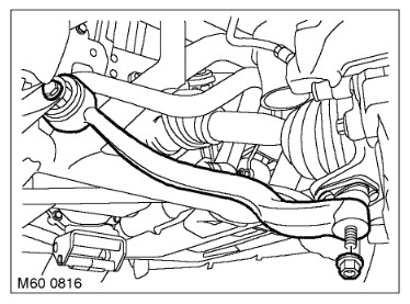
Front Compression Link
The link is described in detail above but the weak spot is the inner bush which oftain tears leading to the front wheels moving back and forward only restrained by the metal, usually leading to a noisy clunky ride.
The other problem with this joint is the massive angles it has to move through while it is twisting the bush against its fixed centre bolted to the sub frame.
You can live with this and swap out the busing every time it fails or replace the standard bushing with something that will tollerate the large angles of movement and last longer. There are plenty of aftermarket options such as the ‘PolyBush’ and simular products from other manufacturers. They will all work better than the stock rubber bush but they will all also ‘ruin’ the ride as they will transmit much more road rumble into the chassis.
Wheel Bearings
Wheel bearings are often sighted as a weak point, in my personal experience I dont consider replacing a wheel bearing as anything more than a service item like a brake pad. That said you need a big press and plenty of tooling to do it efficiently!
Every Other Joint In The Suspension
Lets face it, most of these cars are old now, mine is over 21 years old as I write this and even if the car hadn’t covered 250,000 miles the age would have killed the rubber. Every joint in the suspension needs changing, I can tell you that without even looking because no one changes every joint in the suspension. But you should as it will transform your car.
The Subframes
Ok, before you start pressing old bearings out to put shiny new ones in you better have a poke at your subframes (and wishbones). Make it a serious poke, preferably with a hammer.
No kidding if you can’t whack it with a hammer you better start looking for a new subframe. There is no point in bolting shiny wheels to rotten wishbones bolted to a rusty subframe.
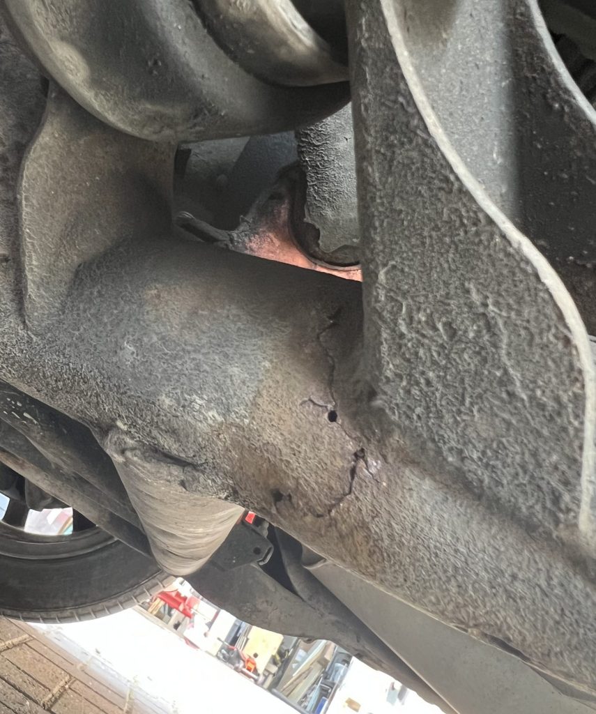
Sometimes you will have to look closely, the image below shows a crack in the front subframe. I knew it was there, you could hear the metal grinding with the steering loads! But it took me a while to find it.
L322 Cracked Front Subframe
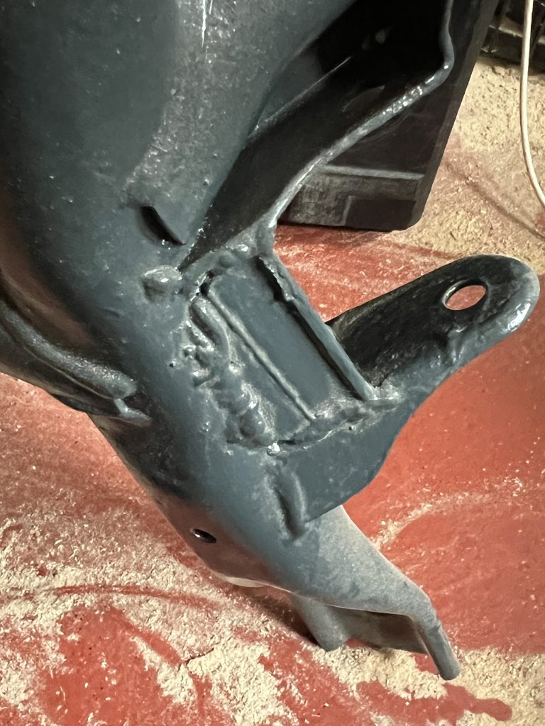
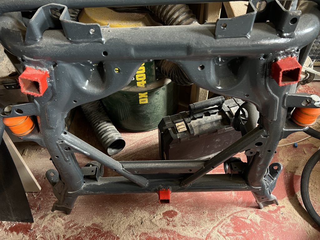
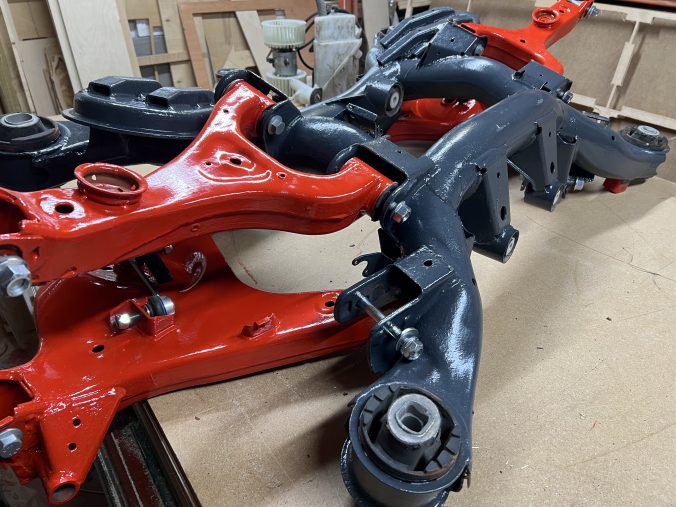
This is one of the areas I modify on Front subframes, see the picture below of the same spot reinforced with a piece of 4mm steel welded in.
L322 front subframe reinforcements.
While we are welding the front subframe I also add jacking points so the trolley jack doesnt slide off the frame! I paint them in a nice contrasting colour to make them easier to find when you are under the car.
Is It Worth It?
The million dollar question! And the answer depends on exactly what you want to do with the old L322.
I love my Range Rover, always have and this particular one, the early model L322 from 2003 or 2004 with the 3.0L diesel straight 6 and built by BMW is my car of choice. For me its worth it.
We have two in the family, mine is the rough one and the wife has a very sweet ‘minter’ that might one day become a body doner for mine!
So for me its worth every penny, and in high performance car terms it is pennies!
Jack it up!
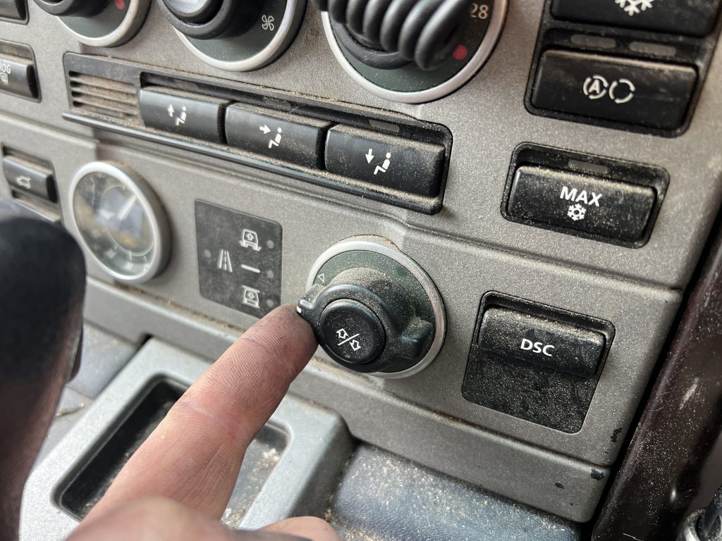
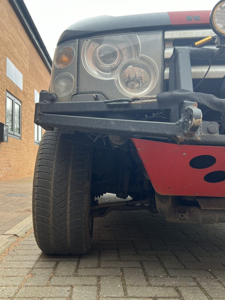
Yeah lets do it! But before we start lets be clear, we want to increase the ground clearance and thats easily done, just twiddle the knob!
Yeah… I know my car is filthy!
And it works, from the data above we can see the front is raised 60mm and the rear by 50mm. the overall travel remains the same at 270mm front and 330mm rear. All it did when you twiddled the knob is move the static height within the fixed limits of the travel.
So 2 inches (50mm) of ground clearance can be found easily by just selecting off road mode. I hear you, you want more.
Wheels and tyres
Yes you can increase ground clearance with bigger wheels and tyres. This is an easy, although expensive way to do it. And it has very limited scope before the additional torque required to over come the added radius of the tyre and therefore force required to rotate them brakes something in the drive train or transmission. That said, and we are not going to spend long on this, the drive train, CV joints, drive shafts etc are the same across the entire range of engines fitted to the L322 so if you are running a remapped TD6 for example you probably dont need to worry as you are still not producing as much power s the V8.
Yes, go up in tyre size but dont go too far. Also, if you genuinely want to improve your cars ability off road then go down in wheel size! The early L322 sported 18 inch wheels and although some might say they look small on the car they were a very good choice allowing 255/65 R18’s to be fitted. they have the same rolling radius as the 255/50 R19’s for example but a larger tyre volume allowing the car to run lower pressures and perform better off road.
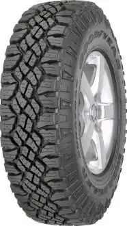
18 inch wheels are about the minimum size you can fit over the front disks without risking fouling anything so find a set of original 18’s and fit some 255/70 R18 Goodyear Wrangler DuraTrac and they should work perfectly. (and so they should at £600 a set!)
Fitting those slightly taller tyres gives another inch of ground clearance.
Body Lift Kits?
A body lift does exactly what it says and using some spacers you can raise the body off the subframes. And thre in lies the problem, you do raise the body but all the bits that would be close to the ground before are still close to the ground. You might improve approach angles, departure height and even high centre, although not necessarily, but the main thing you have dome is move the centre of gravity up.
Most of what a body lift kit can do on a L322 can be done by removing all the overhanging plastic from the body.
Lift Rods
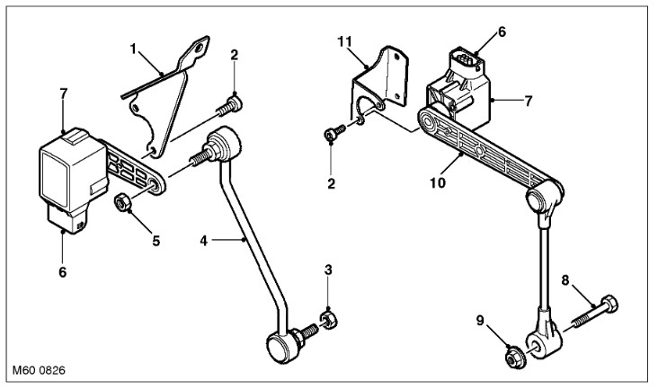
The L322 air suspension knows where it is through the feedback it receives from the 4 height sensors. Front and rear for one side shown in the drawing below.
The sensor is attached via a bracket to the subframe, it has a injection moulded arm which is connected to the wishbone by a linkage rod. This is a system we can mess with!
If we change the length of the rod marked 4 in the above illustration, for example, we extend it; The arm on the sensor is pushed up and as a result the suspension will activate to extend the air bag to push the wishbone down and as a result the wishbone will pull the sensor arm down. The system will continue this process untill it see the sensor returned to its neutral position.
Voila! we have raised the suspension, actually we have raised the whole car and thats on top of the 2 inches from twiddling the knob and another inch from those 255/70 R18’s.
An effective 4 inches (100mm) rise and its probabbly cost less than £1,000.
So whats the problem Stephen?
If you ‘just fitted the adjustable push rods to your stock L322 it will work but you are building in problems for the future.
This is what I reccomend; Replace the inner bushes for top and bottom wishbones front and rear with PolyBush or equivalent, these will rotate with the movement of the wishbones and not resist the movement. The accuracy of the suspension geometry will set better and stay set.
While you are under the car swap out the bushings for the anty roll bars front and rear. The stock rubbers are bonded to the bar so they are a pig to get off but they also apply another complete set of forces on the suspension, not only resisting the roll but also resisting up and down movement! Again PolyBush or something like that. Remeber I said the original bushings are bonded on? Well thats to stop the whole bar moving sideways and fouling the airbags so slide a couple of Jubilee Clips on to the bar between the new bushes to ensure it doesnt move.
From supercars to vintage, rally cars to motorbikes. We will have a selection of the best vehicles from around the world at the weekender!
REFUEL ZONE
Food trucks & bars will be available all day and throughout the evening entertainment.
LIVE MUSIC
DJ’s throughout the day and amazing live music for the Weekender’s evening entertainment.
FAMILY ENTERTAINMENT
Keep the whole family happy throughout the day with rides, bouncy castles, simulator experiences and more entertainment!
TRADE VILLAGE
Browse the amazing selection of traders that will be joining us on the day. Detailers, vehicle security and more!
STUNT SHOWS
We will have entertainment throughout the day from some amazing stunt teams!
CLUB AND DEALER STANDS
A selection of vehicle clubs will be around the showground for you to browse and speak with the organisers.
SPECIAL GUESTS
Talks from guests & YouTubers, sponsors, charities and more throughout the day on the stage.
BURNOUT PAD
Brand new feature for 2024! The place to hear roaring engines and screeching tyres throughout the day. The burnout pad will be keeping things lively by the stage.
COMPETITIONS & AWARDS
Show vehicles will be getting judged and other competitions shall be hosted on the day.
CAMPING/CARAVANS
Tents, caravans and campervans space all avaialble so you don’t have to worry about getting to and from the event all within the day.
CHARITY
We will be working hard to raise as much awareness and money for our charity partners!
Steve’s Steel; Specialist re manufacture of suspension parts, subframes and assosiated components for Land Rover Range Rover L322.
We also love to design, fabricaticate and modify off road veicles, overlanders, wild campers and other unusual 4 wheelers!
Steve’s Steel is based in the tiny city of Ripon in North Yorkshire, just ten minues from the A1 and on the southern boundry of the North Yorkshire Moores and the Yorkshire Dales National Park.
Specialists in early Range Rover L322’s.
We are here to help you keep your L322 on the road and support all you vehicle fabrication needs from modifications to complete builds.